Introduction
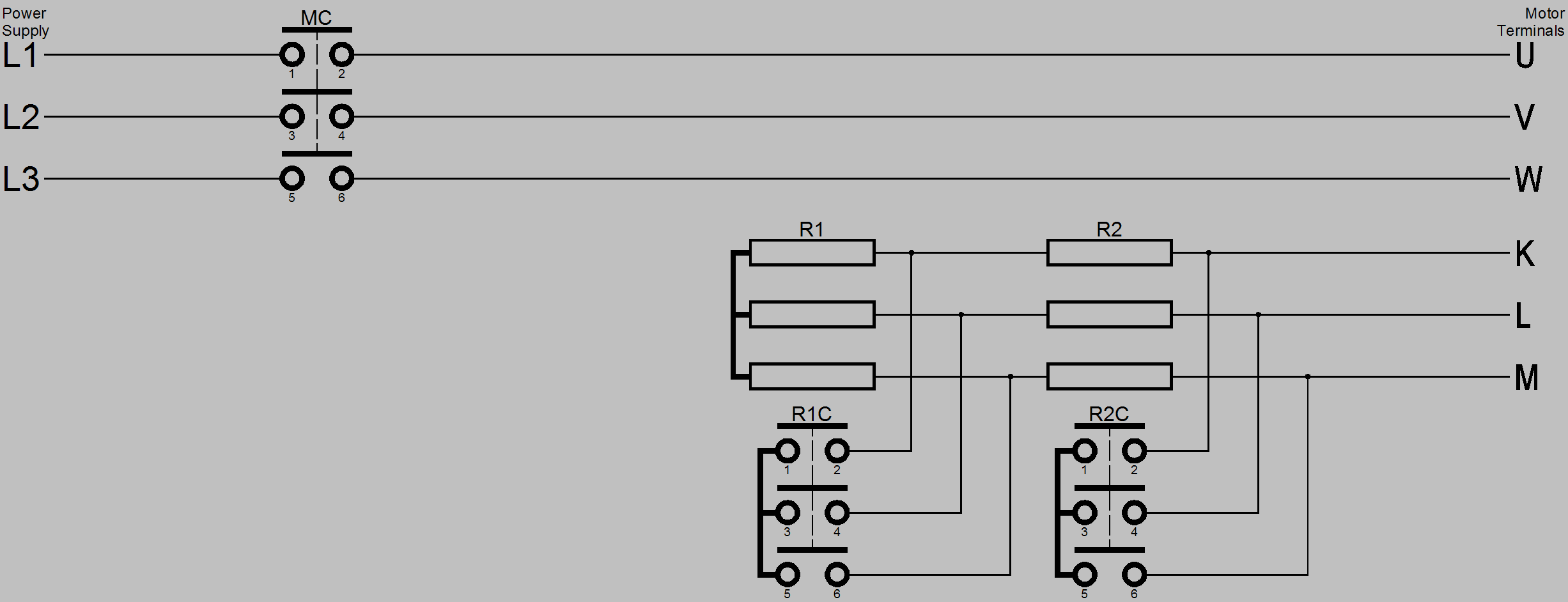
The drawing below shows a two stage rotor resistance starter for clarity and simplicity, additional stages can be added as necessary to suit the characteristics of the motor and it’s driven plant and the limitations of the power supply.
Power Circuit
Control Circuit

Circuit Operation
When the start button is pressed contacts a3-a4 close, the main contactor coil MC is energised which causes it’s main contacts on terminals 1-2, 3-4 and 5-6 to close, it’s normally open auxiliary contact on terminals 13-14 also closes. Power is connected from the power supply to the motor terminals U, V and W and the motor starts to accelerate. The auxiliary contact on terminals 13-14 maintains the supply to the main contactor coil when the start button is released. Simultaneously resistance stage 1 timer R1T energises which starts its timing cycle. After a preset time the resistance stage 1 timer R1T times out the normally open contact 17-18 closes this energises resistance stage 1 contactor R1C causing its main contacts 1-2, 3-4 and 5-6 to close which shorts out resistance stage 1. This reduces the rotor resistance and the motor continues to accelerate. At the same time as R1C energises resistance stage 2 timer R2T energises and starts its timing cycle. After a preset time the resistance stage 2 timer R2T times out the normally open contact 17-18 closes this energises resistance stage 2 contactor R2C causing its main contacts 1-2, 3-4 and 5-6 to close which short out resistance stage 2. This shorts out the external rotor resistance and the motor continues to accelerate to full speed.
To stop the motor the stop button is pressed its contacts a1-a2 open which de-energises the energised contactors and timers thus stopping the motor by removing its power supply and resetting the control circuit.